
What to Send for a Reverse-Engineering Project
The most useful reverse-engineering request explains what the part must do and supplies evidence about its geometry, interfaces, wear, and installation context.
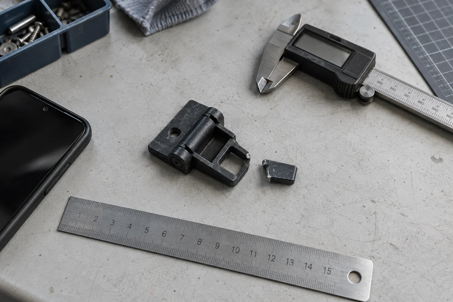
Begin with the purpose, not only the shape
Reverse engineering is not simply copying every visible surface. A useful model needs to reflect why the part exists, what it touches, which features control fit, and whether wear or damage has changed the original geometry. Start by explaining the problem you need to solve and the result you expect.
Describe whether you need a one-time replacement, an editable CAD model, a modified version, a prototype for a fit check, or geometry for a repeat batch. The same physical part can lead to different modeling decisions depending on that goal.
- What the part does and where it is installed.
- What failed, is missing, or needs to change.
- Whether the requested result should match, repair, or intentionally redesign the original.
- The expected quantity and whether an initial fit-check part is acceptable.
Provide the physical part when practical
The original component can reveal details that are difficult to infer from pictures: depth, draft, curvature, hole relationships, mating surfaces, and the way features connect. If the part is broken, include every available piece and avoid altering the fracture or worn area before it is documented.
Also provide the neighboring component, fixture, fastener, or installation area when it controls the fit. A damaged part by itself may not show the intended geometry, while an undamaged mating feature can provide a stronger reference.
Take photographs that explain the geometry
Useful photographs are sharp, evenly lit, and taken from several directions. Include an overall view, orthogonal views when possible, close-ups of interfaces and damage, and at least one image showing the part in its assembly context. Keep the camera far enough away to reduce extreme perspective distortion.
Place a ruler or known reference in the same plane as the feature being documented, but do not rely on a single photograph as a precision measurement. Perspective, lens distortion, and the position of the reference can all affect what can be inferred from an image.
- Front, back, left, right, top, and bottom when those views are accessible.
- Close-ups of holes, tabs, clips, seats, sealing surfaces, and fastener locations.
- The part installed or held beside the assembly it must fit.
- A note identifying which areas are broken, worn, bent, or intentionally asymmetric.
Separate measurements from assumptions
List the dimensions you measured, the tool used, and the location of each measurement. A marked-up photograph or sketch is often clearer than a loose list of numbers. Identify dimensions that control fit separately from dimensions that are approximate or cosmetic.
Every measurement has uncertainty, and the useful level of confidence depends on the application. NIST dimensional-metrology work emphasizes the distinction between a measurement result and its uncertainty. For a project request, the practical lesson is to show how a number was obtained and avoid presenting an estimate as an exact requirement.[1]
- Overall length, width, and height with units.
- Hole diameters, center-to-center spacing, and fastener information.
- Thicknesses, offsets, insertion depths, and clearances that affect assembly.
- A distinction between measured values, nominal values from documentation, and educated estimates.
Explain wear, damage, and intended corrections
A broken or worn component may no longer represent its original shape. Point out rounded edges, stretched holes, missing tabs, cracks, heat distortion, and surfaces polished by contact. If another undamaged example exists, photograph or measure it too.
Do not assume the replacement should copy a failure exactly. Explain whether the goal is faithful recreation, restoration of the likely original geometry, or a deliberate design change. Any change still needs to be reviewed against the part’s function and use conditions.
Include scan data with context
A point cloud or mesh can provide dense surface information, especially for freeform geometry. It does not automatically identify design intent, nominal dimensions, or which surface is functionally critical. Send the original scan format when available, the exported mesh, the scale and units, and notes about any areas that were difficult to capture.
Optical scanning performance can be affected by surface characteristics and the measurement setup. ISO 10360-13 specifically limits its optical 3D measurement-performance framework to surface characteristics within a cooperative range, and NIST has documented multiple error sources in structured-light scanners. Those factors are why critical interfaces may still need direct measurement or physical verification.[2], [3]
Reverse-engineering submission checklist
A complete request does not need to contain every item below. Send what is available, label what is uncertain, and make the intended result clear. The review can then identify the next useful measurement, photograph, scan, or physical reference.
- A concise problem statement and intended result.
- The original part and broken pieces, when practical.
- Multi-angle photographs plus installation context.
- A marked-up sketch or images with dimensions and units.
- Mating parts, fasteners, or interface information.
- Scan files, existing drawings, manuals, or legacy CAD.
- Use environment, quantity, and known safety or regulatory concerns.
- Permission to reproduce the design when intellectual-property rights may apply.
Sources
- National Institute of Standards and Technology. Dimensional Measurement Uncertainty from Data, Part 2. View source (opens in a new tab) Accessed August 12, 2026.
- International Organization for Standardization. ISO 10360-13:2021 — Optical 3D Coordinate Measuring Systems. View source (opens in a new tab) Accessed August 12, 2026.
- National Institute of Standards and Technology. Sources of Errors in Structured Light 3D Scanners. View source (opens in a new tab) Accessed August 12, 2026.