
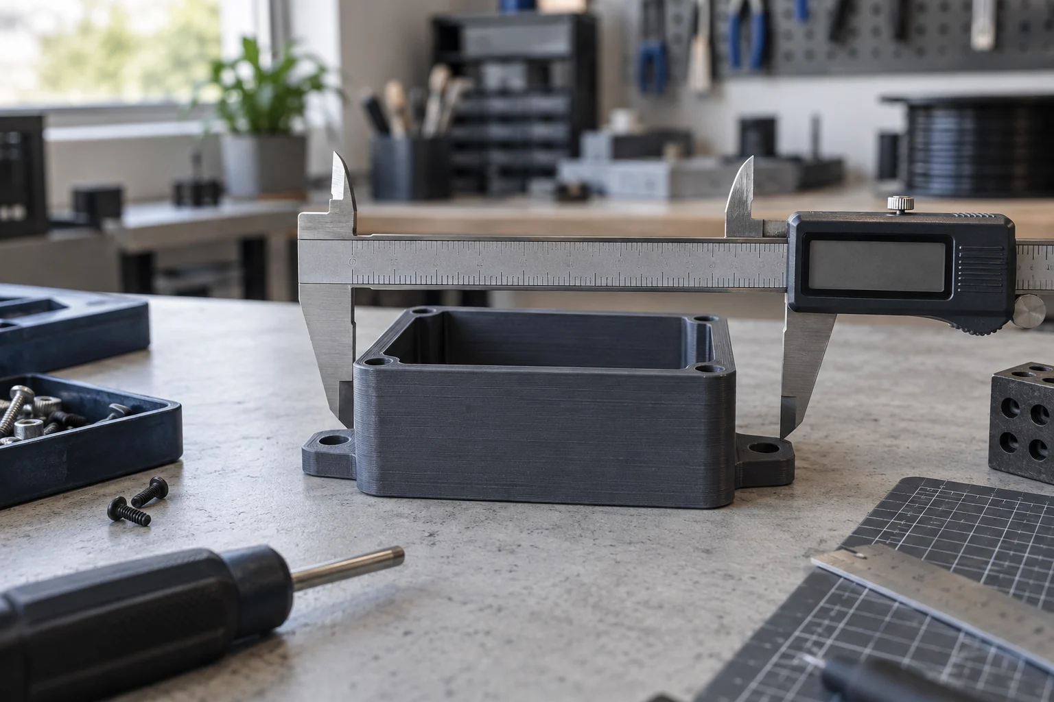
Reverse Engineering for Physical Parts
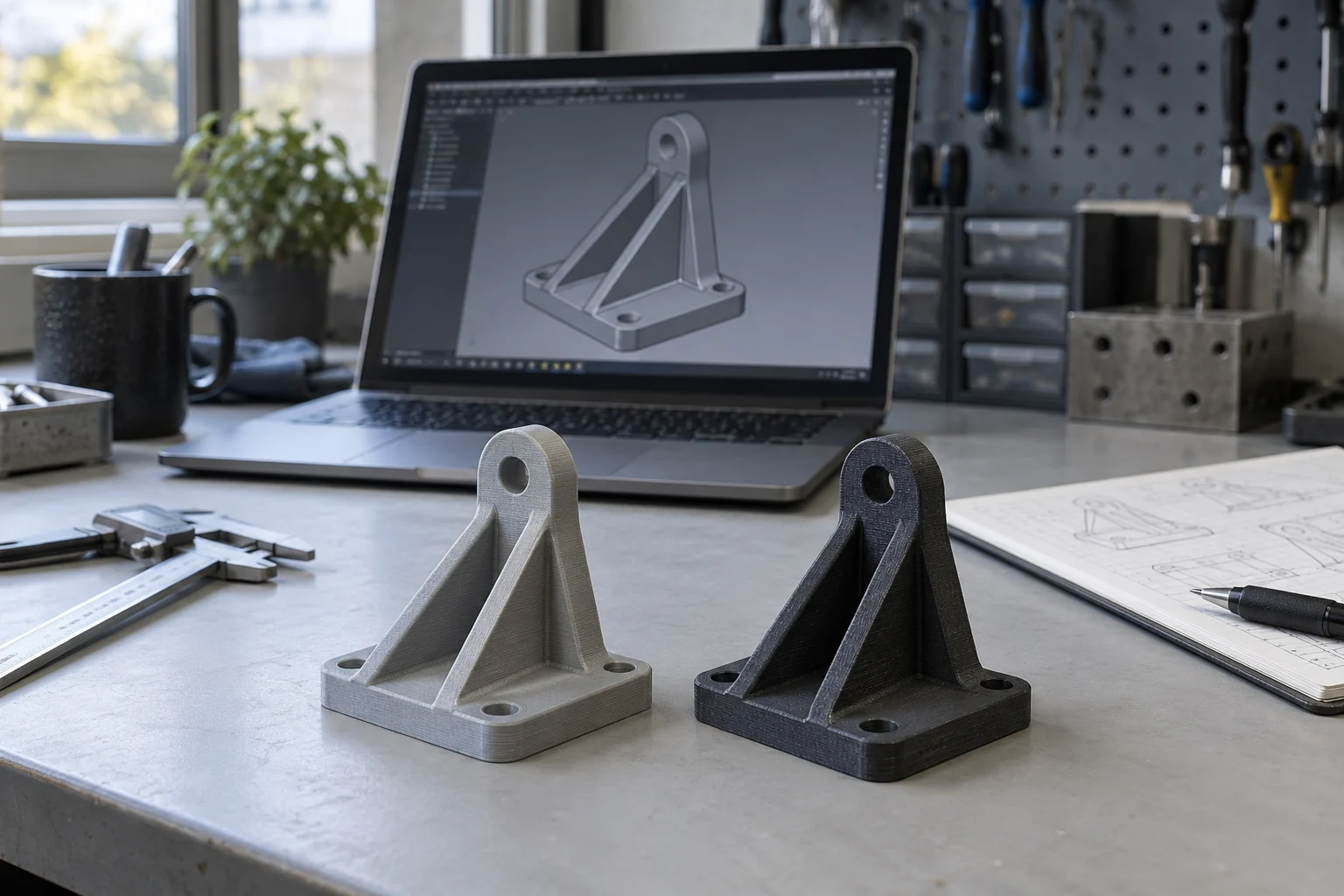
Turn an existing object, damaged component, measurement set, or scan into editable geometry for recreation, modification, or documentation.
Teams that need an existing physical component converted into editable, intentional geometry for recreation, modification, or documentation.
What must the recreated model preserve?
Reverse engineering separates functional design intent from wear, damage, and scanning noise. The right workflow is driven by the surfaces, interfaces, and dimensions that matter in use.
Critical interfaces
Mounting points, mating faces, clearances, alignment features, and assembly constraints usually deserve more attention than nonfunctional surface detail.
Original intent versus current condition
Wear, deformation, repairs, and broken features are documented as evidence, then evaluated rather than automatically reproduced in the new model.
Editable model structure
A surface mesh can preserve shape, while dimensioned CAD makes later changes more practical. The required output determines how much rebuilding is appropriate.
Reverse Engineering
Part assessment
Identify functional surfaces, interfaces, wear, damage, and the information needed to proceed.
Measurement strategy
Select direct measurement, photographic reference, scanning, or a combination.
Editable CAD
Rebuild useful geometry rather than leaving the result as an uneditable scan mesh.
Design changes
Modify the recreated part when the original geometry needs a practical adjustment.
Prototype validation
Use a physical iteration to check assumptions before additional parts are made.
Project inputs and outputs
Project inputs
- Original part and any broken pieces
- Photos of the part and its assembly
- Known dimensions and units
- Existing scans, drawings, or CAD
- Requested changes and final use
- Required file format and quantity
Project outputs
Capture and measurement plan
A defined approach for direct measurements, photographs, scanning, or combined references based on the part and its purpose.
Editable recreated CAD
Purpose-built geometry with important features modeled for the agreed recreation, modification, or documentation use.
Comparison and review outputs
Views, dimensions, or a physical fit-check iteration used to review assumptions when included in the project scope.
Reverse Engineering questions
Is reverse engineering the same as 3D scanning?
No. Scanning captures visible surfaces as a mesh or point-based reference. Reverse engineering interprets that evidence with measurements and design intent to build useful CAD geometry.
What if the original part is damaged?
Damage can often be separated from the intended design when enough intact geometry, assembly context, or reference information remains. Any reconstruction still needs review.
Can the recreated part be changed instead of copied exactly?
Yes. Once the baseline geometry and critical interfaces are understood, requested changes can be modeled and evaluated as a distinct design decision.
What files and measurements will I receive?
Tell us whether the next step needs a mesh, an editable CAD model, a STEP export, a drawing, or a physical prototype. These are different deliverables. The quote identifies the agreed outputs, units, important interfaces, and any dimensions or fit checks included in the work.
How do I start a local or shipped-part project?
Send photos, approximate dimensions, the intended use, and any missing or damaged areas first. We can identify whether the physical part or its mating component is needed. Coordinate a Richland handoff or shipment after the project requirements and handling arrangements are confirmed.
Request a Quote
Teams that need an existing physical component converted into editable, intentional geometry for recreation, modification, or documentation.