
3D Scanning vs. Manual Measurement for Part Recreation
Scanning captures many surface points; direct measurement isolates specific dimensions. Part recreation often benefits from using each method where it is strongest.
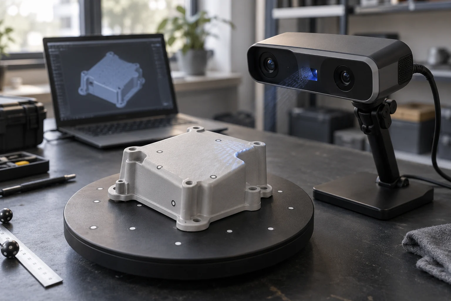
Two ways to collect different kinds of evidence
Manual measurement answers targeted questions: the diameter of a hole, distance between centers, thickness of a wall, depth of a pocket, or width of a slot. 3D scanning captures a dense representation of visible surfaces. Neither method is automatically better; the right choice depends on the geometry and the decision the model must support.
For many reverse-engineering projects, the strongest workflow is hybrid. A scan can establish the overall form while direct measurements anchor functional features and check scale. Photographs, assembly context, drawings, and the physical part remain useful alongside both.
When manual measurement is the clearer choice
Direct measurement is efficient for accessible prismatic geometry and discrete functional dimensions. Flat planes, parallel faces, accessible cylinders, hole spacing, and known fastener interfaces can often be described with a focused measurement plan rather than a dense surface capture.
The plan matters more than collecting a large number of unrelated dimensions. Measurements should connect to datums or reference surfaces so the CAD model can preserve the relationships that control fit. Record units, tool choice, measurement location, and whether a value is nominal, measured, or estimated.[3], [4]
- Accessible holes, slots, bosses, and planar interfaces.
- Features whose center-to-center relationships control assembly.
- Simple forms where a few well-chosen dimensions fully define the shape.
- Checks of critical dimensions taken from a scan or reconstructed model.
When scanning adds useful coverage
Scanning is useful when the object has freeform curvature, blended transitions, asymmetric contours, textured forms, or many surfaces that would be slow or ambiguous to describe one dimension at a time. It can also preserve the spatial relationship between features that are difficult to reference with simple hand tools.
The scan only captures surfaces the system can observe under the measurement conditions. Deep recesses, occluded areas, thin edges, reflective regions, translucent material, and very dark or otherwise uncooperative surfaces can require a different setup or supplementary evidence. ISO and NIST resources both treat surface characteristics and setup as relevant to optical measurement performance.[1], [2]
- Organic or sculpted surfaces with continuous curvature.
- Complex exterior contours that need broad spatial coverage.
- Asymmetric shapes where repeated manual sections would be difficult to register.
- A digital surface reference for later reverse modeling or documentation.
A scan mesh is not automatically editable CAD
Scan output commonly represents sampled points or a triangulated surface. STL, for example, describes geometry as triangular facets rather than the structured features of a product model. A mesh can be a strong geometric reference, but it does not inherently identify a hole as a nominal cylinder, a face as a datum, or a worn edge as damage.[5]
Reverse modeling interprets that evidence and builds geometry appropriate to the project. That may involve fitting planes and cylinders, reconstructing curves, restoring symmetry, preserving selected freeform areas, and validating interfaces against direct measurements or the physical assembly.[3]
Questions that determine the measurement plan
Before choosing a scanner or measuring every visible feature, define the output and the risk of getting a feature wrong. A display model, a fit-check prototype, an editable design reference, and a working replacement part do not require the same evidence.
- Which surfaces or dimensions control fit and function?
- Is the shape mostly prismatic, mostly freeform, or a combination?
- Can all important surfaces be seen and accessed?
- Is the original part worn, broken, flexible, reflective, translucent, or otherwise difficult to capture?
- Does the deliverable need to be an editable CAD model, a mesh reference, or both?
- What physical check will confirm that the reconstructed geometry answers the project need?
A practical hybrid workflow
Start with the function and identify critical interfaces. Capture the broad form with scanning when it adds value, measure accessible functional features directly, and document areas the scanner could not observe. Build the CAD model around those references, then compare the result with the source evidence before deciding whether a physical prototype is needed.
This approach avoids treating a dense scan as automatically correct or a short list of measurements as automatically complete. Each method contributes evidence to a model that still needs project-specific review.
Sources
- International Organization for Standardization. ISO 10360-13:2021 — Optical 3D Coordinate Measuring Systems. View source (opens in a new tab) Accessed August 12, 2026.
- National Institute of Standards and Technology. Sources of Errors in Structured Light 3D Scanners. View source (opens in a new tab) Accessed August 12, 2026.
- National Institute of Standards and Technology. Dimensional Metrology Algorithm Testing. View source (opens in a new tab) Accessed August 12, 2026.
- National Institute of Standards and Technology. Dimensional Measurement Uncertainty from Data, Part 2. View source (opens in a new tab) Accessed August 12, 2026.
- Library of Congress. STL (STereoLithography) File Format Family. View source (opens in a new tab) Accessed August 12, 2026.